
Commercial Disclosure: The HiMASSi® Editorial Team combines local Australian market insight with the battery engineering and manufacturing expertise of Shenzhen Himax Electronics Co., Ltd. to provide practical, technically informed content for businesses, OEMs, system integrators, and industry professionals. As Himax Electronics’ official flagship brand in Australia, HiMASSi® focuses on LiFePO4 batteries, custom battery solutions, BMS technology, charging systems, battery selection, and application-specific power solutions. Our content covers technical guidance, industrial and commercial applications, product updates, and HiMASSi® news. All content reflects HiMASSi®’s official editorial perspective and is intended to help Australian customers evaluate battery solutions based on their application requirements, operating conditions, system compatibility, and project needs.
Key Takeaways
- A BMS for a high-voltage marine lithium battery needs to do more than monitor voltage, current and temperature. It should also work in coordination with high-voltage distribution, charging equipment, thermal management and the vessel’s power management system.
- BMS selection should not be based solely on the number of series-connected cells it supports. Operating voltage range, insulation design, fault response, communication failure handling and control power reliability can all affect system compatibility.
- Battery protection and continuity of vessel power need to be considered together. Depending on the level of risk, a fault may call for an alarm, power derating, branch isolation or an emergency shutdown.
- A BMS does not replace battery compartment fire protection, ventilation, gas detection or thermal propagation protection, nor can it prevent every thermal runaway event on its own.
- Shipbuilders and OEMs should identify the applicable regulations, classification rules and acceptance scope early in the project, then validate the design through system integration and fault testing.
Why Do High-Voltage Marine Lithium Batteries Require a Dedicated BMS Assessment?
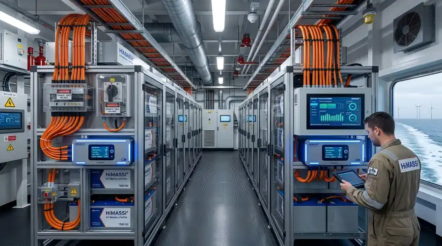
In electric vessels, hybrid vessels and onboard energy storage systems, batteries may be used for propulsion, peak shaving, auxiliary power or backup power. Different applications place different requirements on the BMS.
In this article, “high-voltage marine lithium batteries” mainly refers to battery systems used in these applications with relatively high DC bus voltages. The exact voltage classification should be determined by the standards applicable to the project rather than simply adopting definitions used in the automotive industry.
Compared with smaller standalone batteries, these systems typically have more cells connected in series, greater stored energy and more complex control interfaces. The BMS therefore needs to answer more than simply “how much charge is left?” It also needs to address questions such as:
- How much charging and discharging power can the battery currently accept or deliver?
- Is there an abnormal condition in a particular battery string, and does it need to be isolated?
- How should the charger and propulsion equipment respond if communication is lost?
- If a controller or control power branch fails, will the required protection functions remain available?
For this reason, BMS selection for high-voltage marine batteries should begin with the vessel’s operating conditions and overall system architecture, rather than simply increasing the series-cell capacity of a conventional battery protection board.
What Core Functions Does a High-Voltage Marine Lithium Battery BMS Need?
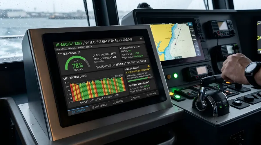
From a manufacturing and integration perspective, BMS requirements can be grouped into four areas: monitoring, estimation, protection and coordinated control. The table below can serve as a starting point for OEMs preparing a technical specification, although the actual parameters need to be determined based on the cell type, system architecture and project requirements.
| Functional Area | Technical Details to Define | Questions OEMs Should Verify |
| Voltage monitoring | Individual cell or parallel cell-group voltage, total voltage and sampling fault diagnostics | Can the system identify local abnormalities rather than monitoring only total pack voltage? |
| Current monitoring | Charge/discharge current, measurement range, accuracy and zero-point drift | Does the measurement range cover both continuous loads and short-duration peaks? |
| Temperature monitoring | Sensor locations, temperature differences, and detection of open- or short-circuit sensors | Are the measurement points representative of locations where thermal risks may develop? |
| State estimation | SOC, SOH and available charge/discharge power | Has the estimation been validated under actual vessel operating profiles? |
| Cell balancing | Balancing method, current, activation conditions and thermal impact | Can the balancing strategy perform effectively within the actual operating window? |
| Protection control | Overcharge, over-discharge, overcurrent, abnormal temperature and fault classification | Which component executes the required action after a threshold is triggered? |
| High-voltage coordination | Pre-charge, contactor feedback and insulation monitoring interface | Does the logic cover faults such as failed power-up and welded contacts? |
| Communication and logging | Data protocols, timeout handling, event logs and version information | Can the vessel systems correctly interpret and act on BMS limits and commands? |
For modules containing cells connected in parallel, the BMS will typically measure the terminal voltage of the parallel group rather than the condition of every individual cell within that group. Cell selection and matching, interconnection design and thermal management therefore remain important parts of manufacturing quality.
What Are the Requirements for High-Voltage Insulation, Pre-Charge and Contactor Control?
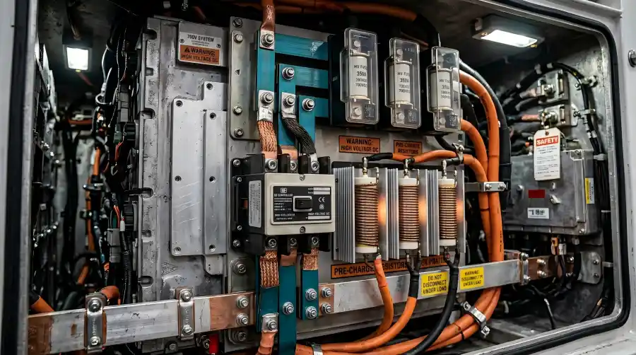
Insulation Design Needs to Cover the Full Voltage Range
Insulation assessment should not be based on nominal voltage alone. The maximum charging voltage, operating transients, installation environment and applicable standards also need to be considered.
Isolation between the BMS measurement circuits, communication interfaces and low-voltage power supply should match the system architecture. Creepage distance, clearance and dielectric withstand capability should also be determined according to actual operating conditions, rather than relying solely on a claim that a BMS “supports” a particular voltage platform.
For systems using insulation monitoring, the location of the insulation monitoring device, grounding arrangement, alarm thresholds and response strategy should be clearly defined. The insulation monitoring device does not necessarily need to be integrated into the BMS, but the responsibilities of the monitoring device, BMS and vessel alarm system should be clearly allocated.
Pre-Charge Logic Needs to Confirm That Pre-Charging Has Succeeded
When a battery is connected to equipment with DC bus capacitors, a high inrush current may occur. Whether pre-charging is required, and whether it is handled on the battery side or converter side, should be determined during system design.
Engineering reviews should consider:
- Whether the bus voltage reaches the required level for main contactor closure within the specified time;
- Whether main contactor closure is prevented if pre-charging fails;
- Whether repeated pre-charge attempts could overheat the pre-charge resistor;
- Whether contactor feedback is consistent with the actual DC bus condition.
Using only a fixed time delay without checking the voltage response may leave some fault conditions undetected.
The BMS Needs to Coordinate with DC Protection Devices
A disconnect command from the BMS does not necessarily mean that a contactor can safely interrupt every possible fault current.
Contactors, fuses and DC circuit breakers should be coordinated according to DC voltage, prospective short-circuit current and interrupting capacity. The protection strategy should clearly distinguish between the faults detected and controlled by the BMS and those that must be interrupted by dedicated protection devices.
Why Should Protection Logic Be More Sophisticated Than “Fault Detected, Power Off”?
Marine battery protection involves both battery safety and continuity of propulsion and critical loads.
For example, when temperature approaches an allowable operating limit, the system may first reduce output power and request additional cooling. If a fault reaches a level requiring isolation, disconnection should then occur according to an assessed and validated protection strategy. The battery should not be allowed to continue operating beyond confirmed safety limits simply to maintain propulsion.
The following fault classification can be used as a framework for project discussions:
| Fault Condition | Possible Response | What Needs to Be Validated |
| Temperature approaching an operating limit | Alarm, limit charging/discharging power, adjust cooling | Can stable operation be maintained after the thermal management system responds? |
| Cell voltage approaching a limit | Restrict current in the relevant direction | Does the charger or converter respond within the required time? |
| Fault in one battery string | Isolate the affected string where the architecture allows | Can the remaining power sources support the required loads? |
| Communication loss | Derate power or shut down according to a predefined strategy | Are timeout settings and equipment responses consistent across the system? |
| Serious electrical fault | Interrupt the fault using the appropriate protection device | Are protection coverage, interrupting capacity and selectivity adequate? |
The table is an engineering discussion framework, not a fixed protection strategy for every vessel. ABS requirements for lithium-ion batteries in marine applications address the BMS, emergency disconnection, monitoring and alarms, and system requirements when batteries are used as a main source of power as separate but related areas. This highlights the need to coordinate these functions across the complete system. Reference: ABS Requirements for Use of Lithium-Ion Batteries in the Marine and Offshore Industries, 2024
What Needs to Be Defined for Communication Between the Marine BMS, PMS and EMS?
PMS generally refers to a Power Management System, while EMS generally refers to an Energy Management System. The division of functions can vary between vessels and should be defined in the project interface documentation.
The data supplied by the BMS should extend beyond total voltage and SOC. It should also include the currently permitted charging current, discharging current or power limits, as well as alarms, faults and availability status.
“CAN communication supported” only describes part of the interface capability and does not, by itself, demonstrate interoperability. OEMs should also define:
- Message identifiers, units, scaling and update intervals;
- Heartbeat, timeout and invalid-data handling;
- Priority of charge and discharge permission signals;
- Fault acknowledgement and recovery conditions;
- Whether automatic reconnection is permitted after communication is restored.
For example, if the BMS reduces the allowable charging current to zero but the charger continues to operate using an earlier command, there is a gap in system coordination. Interface acceptance testing therefore needs to verify that connected equipment acts on BMS commands, not merely that the data can be displayed on a screen.
How Should SOC, SOH and Available Power Estimation Be Validated?
SOC refers to State of Charge, while SOH refers to State of Health. For marine projects, the sustainable power and usable energy available under current operating conditions should also be considered.
SOC is not a directly measured value. Current sensor offset, temperature variation, ageing and long periods without calibration opportunities can all affect the estimate. LiFePO4 batteries have relatively flat voltage characteristics across parts of their operating range, making terminal voltage alone an unreliable indicator of remaining charge in those regions.
OEMs should not rely solely on an “SOC accuracy” figure stated without test conditions. Instead, suppliers should specify the test temperature, load profile, initial conditions, test duration and reference measurement method. SOH should also be clearly defined as capacity-based, resistance-based or power-capability-based to avoid direct comparisons between different definitions.
DNV has highlighted that reliable estimation of available energy and battery health is relevant to propulsion, manoeuvring and operational decision-making in marine applications. Reference: DNV Maritime Battery Degradation Monitoring and Prediction
What Do the Marine Environment and Thermal Runaway Risks Mean for the BMS?
Marine installation environments may involve humidity, condensation, salt exposure, vibration, temperature fluctuations and electromagnetic interference. Environmental test conditions should be determined according to the actual installation location rather than applying a single protection rating to every BMS.
Design reviews should cover PCB protection, connector sealing, harness retention, shielding and grounding, and sensor reliability. Even when the BMS is installed inside a battery cabinet, condensation within the enclosure and cooling-system faults should still be considered.
At the same time, a BMS can reduce some risks by monitoring battery conditions and limiting operation, but it cannot replace thermal propagation protection, ventilation, fire protection or gas detection. An internal cell fault may continue to develop even after external current has been interrupted.
The Australian Maritime Safety Authority (AMSA) also addresses lithium battery installation, maintenance, monitoring and risk management as part of the broader approach to electrical safety on vessels. Reference: AMSA – Electrical Safety: Reducing the Risk of Electrical Faults and Fires
What Documentation Should Shipbuilders and OEMs Request from Suppliers?
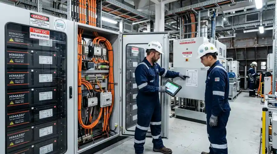
When sourcing a BMS for a high-voltage marine lithium battery system, the scope of acceptance should extend beyond the individual control board to include the complete battery system and its interfaces.
| Documentation or Test | Main Purpose |
| Battery and BMS technical specifications | Confirm voltage, current, temperature and operating limits |
| System block diagram and Interface Control Document (ICD) | Define responsibilities between the BMS, power distribution, charging equipment and vessel control systems |
| Protection threshold and action matrix | Verify trigger conditions, delays, actuating devices and recovery conditions |
| Risk and failure analysis | Assess sensor failures, loss of control power and other fault conditions |
| Environmental and EMC test reports | Confirm that test conditions correspond to the intended installation environment |
| Software version and change records | Maintain traceability across production deliveries and ongoing maintenance |
| Factory testing and system integration records | Verify protection logic and the response of external equipment |
| Certificates and statements of applicability | Confirm the models, configurations and limitations covered by certification |
For systems with complex control logic, Hardware-in-the-Loop (HIL) testing can be used to simulate sensor faults, communication failures and changing load conditions. DNV includes BMS hardware-in-the-loop testing among its validation services for marine battery systems. Reference: DNV Battery and Hybrid Ships Services
Frequently Asked Questions About High-Voltage Marine Lithium Battery BMS
Does Passing IEC 62619 Testing Mean a Battery Can Be Used on Any Vessel?
No. IEC 62619:2022 covers safety requirements for secondary lithium cells and batteries used in industrial applications, with marine applications included among its examples. However, compliance with IEC 62619 does not by itself constitute installation approval or classification acceptance for a complete vessel project. The applicable project rules and the scope of the relevant certificates still need to be confirmed. Reference: IEC 62619:2022
Does a High-Voltage Marine BMS Need Dual Controllers?
Not necessarily. The need for redundancy, independent protection channels or backup control power should be determined according to the battery’s function, the consequences of failure and the applicable project requirements. Even two controllers may not provide the intended level of redundancy if they share a power supply or actuating component that represents a single point of failure.
Can Standard Low-Voltage LiFePO4 Batteries Be Connected in Series to Create a High-Voltage Marine Battery Bank?
This should only be considered where the products are explicitly designed to support the required series configuration and the complete system has undergone appropriate design validation. Module insulation, internal switching-device voltage ratings, communication isolation and fault-interruption capability all need to be assessed. Simply adding the individual battery voltages together is not sufficient.
Is Active Balancing Better Than Passive Balancing for Marine Batteries?
It depends on cell consistency, operating window, balancing requirements, heat generation and system complexity. Active balancing can transfer energy between cells but adds circuitry and control requirements. Passive balancing is comparatively simpler but is limited by balancing current and heat dissipation.
Is the Battery System Free of High Voltage Once the BMS Is Powered Off?
No. Loss of BMS control power, opening of the contactors and confirmation that no hazardous voltage remains are different states. The battery itself continues to store energy, and residual voltage may remain on the DC bus. Maintenance procedures should therefore include isolation, discharge and verification of absence of voltage.
Can OEMs Modify All BMS Protection Parameters?
Protection parameters should not be freely adjustable without defined limits. Parameter changes should remain within validated ranges and be subject to access control, logging and version management. Changes outside the validated limits of the cells or system require reassessment and, where necessary, additional testing.
When Should Compliance Requirements Be Confirmed for Australian Marine Projects?
Ideally, during the concept and design stage. Vessel type, intended use, operating area and classification status can all affect the applicable requirements. Suppliers, shipyards, system integrators and relevant approval bodies should establish the applicable standards, editions and acceptance scope early in the project to reduce the risk of discovering missing interfaces or documentation after equipment has been delivered.
About HiMASSi®
HiMASSi® is the official flagship brand of Shenzhen Himax Electronics Co., Ltd. for the Australian market, providing local market support for battery products and application requirements. HiMASSi® focuses on LiFePO4 batteries, custom battery solutions, Melbourne-based support and collaboration with factory engineering teams. Learn more about HiMASSi® Australia
If you are a shipbuilder, system integrator or OEM evaluating a marine battery solution, you can provide HiMASSi® with your DC bus voltage range, continuous and peak power requirements, operating profile, installation environment, communication interfaces and project compliance requirements to discuss battery selection and customisation. For high-voltage marine applications, product configuration, BMS functions and certification scope should be confirmed against the technical requirements, specifications and validation results of the specific project.